
Wiring harness sheath and branch routing fixing process: sheath selection, branch angle, arrangement of fixing points, and inspection records
Process boundaries: What does the sheath need to address
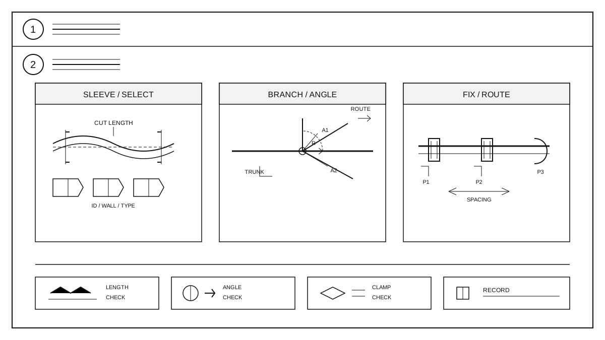
The sheath is responsible for isolating wear, guiding the direction of branches, reducing vibration and friction, and providing operators with a clear reference for routing. The sheath does not bear tensile forces and cannot replace the fixation at the root of branches. If the sheath does not match the harness's outer diameter, the number of branches, bending radius, or installation space, first modify the sheath or adjust the routing rather than forcibly flattening it with ties. The drawings should indicate the sheath model, cut length, opening direction, branch angle, and fixation point positions, which should be checked on site according to the drawings.
Sheath Selection and Cutting
The protective sleeve is selected according to material, inner diameter, wall thickness, length, and opening type. Flexible, bend-resistant sleeves are chosen for areas that experience continuous bending; heat-resistant and wear-resistant sleeves are selected for areas near heat sources or moving parts; for branches that need post-installation, open-type or spiral-wound sleeves are used. Cut lengths according to the drawing; the cut must be even, without burrs, tears, or excessive stretching. The opening of the open-type sleeve should face the maintenance side, not towards moving parts or sharp edges. After cutting, first perform a test fit to ensure the sleeve can cover the base of the branch without pressing against the connector.
Branch angle and alignment layout
The branches should be drawn from the main trunk according to the blueprint. A common practice is to smoothly separate them along the direction of the main trunk, avoiding multiple branches emerging from the same point. Leave a sufficient curve at the base of the branch, and do not allow the sheath to bend at a right angle. The routing should avoid high-temperature surfaces, moving parts, sharp edges, and maintenance paths; if crossing is necessary, add isolation or change the height. The routing of the main trunk and branches should be pre-arranged on the tooling board to ensure that sheaths do not press against each other and that branches are neither suspended nor in contact with the vehicle body.
Fixed Point Layout and Fixing Method
Fixed points are arranged according to the drawings, typically set at the root of branches, at the ends of sheaths, and at the midpoint of long runs. Clips, cable ties, and brackets are selected based on conductor diameter, sheath outer diameter, and mounting surface. After fixing, the sheath must not be deformed, flattened, or rotated with the branch. Cable ties must not be placed directly over sheath seams, and clips must not be installed at an angle. The spacing of fixed points follows technical documentation, with a fixed point left before and after bends. The fixing sequence is first the main line, then the branches; first position, then tighten, to avoid transferring stress to the connector end.
Inspection, Rework, and Records
Check the sheath model, cutting length, opening direction, branch angle, number of fixing points, clip direction, cable tie allowance, and sheath surface condition. During the first-piece inspection, confirm the routing and fixing points; during inspection sampling, check the branch roots and bends; for the last-piece review, check whether the sheath has slipped. When reworking, release the fixing points first before adjusting the sheath; do not pull the sheath directly. After replacing the sheath, reconfirm the branch angle and fixing points. For downstream custom interfaces, see custom harness capability.